
Fibre optic cable splicing is essential for connecting two fibre optic cables, maintaining signal quality and supporting high-speed data transmission.
This guide covers the types, and components of fibre optic cable splicing, along with the tools and preparation needed for both fusion and mechanical splicing.
We will also explore testing, quality assurance, troubleshooting, and best practices for reliable splicing.
Whether you’re a technician, engineer, IT professional, or enthusiast, this guide aims to provide comprehensive knowledge and practical insights into fibre optic cable splicing.
What is Fibre Optic Cable Splicing?
Fibre optic cable splicing involves joining two fibre optic cables end-to-end to create a continuous optical path for signal transmission.
This process is used for installing long cable runs or repairing damaged cables. There are two main methods: fusion splicing and mechanical splicing.
Fusion splicing uses an electric arc to weld the fibre ends together, resulting in a permanent, low-loss connection.
Mechanical splicing aligns the fibre ends within a splice enclosure, using index matching gel to minimise signal loss.
Key terms include attenuation, splice loss, and back reflection. Splicing is widely used in telecommunications, data centres, and cable television networks.
Importance of Splicing in Fibre Optic Networks
A splicing fibre optic cable is needed for maintaining high-quality network performance by joining fibre ends to reduce signal loss.
This is required for long-distance data transmission in telecommunications and data networks.
Splicing provides a stable and reliable connection, minimising the need for frequent maintenance.
Proper splicing techniques prevent network downtime and support continuous service, especially in essential settings like data centres and telecommunications infrastructure.
By reducing signal loss and reflection, splicing improves overall network performance and reliability, making it a fundamental technique for effective network connections.
Types of Fibre Optic Splices
There are two primary methods for splicing fibre optic cables: fusion splicing and mechanical splicing.
Fusion Splicing
Fusion splicing involves welding the fibre ends together using an electric arc, creating a strong, permanent connection with minimal signal loss.
This method is ideal for high-performance networks.
Mechanical Splicing
Mechanical splicing aligns the fibre ends within a special enclosure using index-matching gel.
It provides a quicker, less equipment-intensive method but may result in slightly higher signal loss.
Comparison and Use Cases
Fusion splicing is preferred for long-term installations and useful applications due to its lower signal loss and greater strength.
Mechanical splicing is useful for temporary repairs, testing, or quick splicing needs.
Both methods are essential for technicians and engineers working with fibre optic networks.
Components of a Fibre Optic Cable
Fibre optic cables are composed of several key components:
Core and Cladding
The core, made of glass or plastic, transmits light signals.
Surrounding the core is the cladding, which has a lower refractive index to keep the light signals confined within the core through total internal reflection.
Buffer Coating
The buffer coating protects the cladding from physical damage and environmental factors like moisture and temperature changes.
Materials such as acrylic and silicone are commonly used.
Strength Members
Strength members, made from materials like aramid yarn (Kevlar), steel, or fibreglass, provide additional durability and protection, helping the cable withstand mechanical stresses.
Outer Jacket
The outer jacket, made from materials like PVC, polyethene, or polyurethane, protects the cable from physical damage, chemicals, and environmental hazards.
It also contributes to the cable’s flexibility, making it easier to handle during installation.
The user must understand these components to perform effective splicing and installation, including the reliability and performance of the network.
Types of Fibre Optic Cables

Fibre optic cables come in various types, each designed for specific applications:
Single-mode Fibre
Single-mode fibre has a small core diameter (around 9 microns), allowing for higher bandwidth and longer transmission distances. It is commonly used in telecommunications, internet, and cable television networks.
Multi-mode Fibre
Multi-mode fibre has a larger core diameter (50 or 62.5 microns), suitable for shorter-distance applications like local area networks (LANs) and data centres.
Simplex vs. Duplex Cables
Simplex cables consist of a single fibre, used for one-way data transmission.
Duplex cables have two fibres for bi-directional communication, commonly used in fibre optic networking equipment.
Specialty Fibre Optic Cables
Speciality cables, such as bend-insensitive and ruggedized cables, are designed for specific applications that require unique properties.
These are used in military communications, industrial settings, and medical equipment.
Understanding the different types of fibre optic cables and their applications helps in selecting the right cable for each need and performing effective splicing.
Understanding Fibre Optic Cable Construction
The construction of fibre optic cables is designed to protect the fibres and to allow for efficient data transmission.
Key components include the core and cladding, buffer coating, strength members, and outer jacket.
The core transmits light signals, while the cladding reflects light back into the core. The buffer coating shields the fibres from damage, and the strength members provide durability.
The outer jacket protects against physical and chemical damage, contributing to the cable’s flexibility.
Understanding these components is needed for selecting appropriate splicing methods and tools, and the integrity and performance of the network.
Tools and Equipment for Splicing
Proper tools and equipment are essential for successful fibre optic splicing.
Fusion Splicing Equipment
Fusion Splicers
These devices weld the fibre ends together using an electric arc, this allows for a precise match and creates a strong, permanent bond.
Popular models include the Fujikura 70S and the Sumitomo T-71.
Electrode Maintenance
Regular maintenance of fusion splicer electrodes is needed for a strong performance. Cleaning and replacing electrodes as needed maintains splice quality.
Splice Protection Sleeves
These protect the spliced area from physical damage and environmental factors. They are placed over the splice and heat-shrunk to secure the connection.
Calibration and Setup
Proper calibration of fusion splicers is necessary for accurate splicing. Follow the manufacturer’s instructions for setup and calibration to the correct operation.
For more detailed information on the tools needed, explore our Splice Modules.
Mechanical Splicing Tools
Mechanical Splicers
These devices align the fibre ends within a splice enclosure using index-matching gel, providing a quick and easy method for splicing.
Popular models include the 3M Fibrlok and the Tyco AMP.
Index Matching Gels
These gels reduce signal loss by matching the refractive index of the fibre ends.
Protective Enclosures
Enclosures protect mechanical splices from physical damage, environmental factors, and stability.
Alignment Tools
Precision cleavers and matching fixtures prepare and align the fibres accurately for a low-loss splice.
Having the right tools and maintaining them properly is required for achieving high-quality fibre optic splices.
Fibre Cleavers and Strippers
Fibre cleavers and strippers are required tools in the splicing process.
Fibre Cleavers
Fibre cleavers cut the fibre optic cable with precision. A good cleaver makes a clean, flat end face on the fibre, essential for both fusion and mechanical splicing.
Popular models include the Fujikura CT-30 and the Sumitomo FC-6S.
Regular maintenance, such as cleaning the blade and replacing it when worn, allows for consistent performance.
Fibre Strippers
Fibre strippers remove the protective coatings from the fibre without damaging the glass core and cladding.
Proper stripping is meant to prevent fibre breakage and give the user accurate splicing. Tools like the Miller ACS-2 and the Ripley Miller MSAT 5 are commonly used.
Strippers come with various settings to accommodate different fibre sizes and coatings.
Correct use and maintenance of fibre cleavers and strippers are fundamental for preparing fibres for splicing, leading to successful splicing outcomes.
Proper preparation is needed for successful fibre optic splicing. This involves inspecting, cleaning, stripping, and cleaving the fibres.
Inspecting and cleaning the cables before splicing removes dirt, dust, or contaminants that can affect splice quality.
Use fibre optic inspection microscopes to check for debris or damage. Cleaning tools such as lint-free wipes and isopropyl alcohol are used to clean the fibre ends thoroughly.
Fibre Stripping Techniques
Stripping the fibre involves removing the buffer coating without damaging the core and cladding.
Use precision fibre strippers to remove the coating in layers, as this gives you a clean and undamaged fibre.
Proper technique avoids nicks or scratches that could weaken the fibre.
Cleaving the Fibre
Cleaving cuts the fibre to create a flat, smooth end face, which can be used for both fusion and mechanical splicing.
Use a high-quality fibre cleaver to achieve a precise cut.
The cleaver should be well-maintained, with a sharp blade to provide a clean cleave.
Follow the manufacturer’s instructions for proper cleaving techniques.
For more information on preparing fibre for splicing, visit our guide on how to terminate a fibre optic cable.
By meticulously inspecting, cleaning, stripping, and cleaving the fibres, technicians can prepare them for effective splicing, achieving low-loss splices and reliable network performance.
Fusion Splicing Process
Fusion splicing joins two optical fibres by melting their ends together to form a continuous, low-loss connection. Here are the key steps:
Aligning and Merging Fibre Ends
The first step is to precisely align the fibre ends using a fusion splicer, which has high-precision motors for sub-micron accuracy. Proper alignment is crucial as it minimises signal loss and allows for a strong splice. Here’s a more detailed breakdown of this step:
- Preparation: Before aligning the fibres, ensure that both fibre ends are clean and cleaved properly. A good cleave provides a flat, perpendicular surface which is essential for a quality splice.
- Loading Fibres: Insert the fibres into the fusion splicer. The splicer typically holds the fibres in V-grooves or clamps to keep them stable during alignment.
- Alignment Process: The splicer uses cameras and image processing software to align the fibre cores. It adjusts the position of the fibres using high-precision motors, achieving sub-micron accuracy.
- Core Alignment: In core alignment splicers, the alignment is done by viewing the fibre cores directly. This method offers the highest precision and is suitable for single-mode fibres.
- Cladding Alignment: In cladding alignment splicers, the alignment is done by aligning the outer cladding of the fibres. This method is faster but may not be as precise as core alignment, making it more suitable for multimode fibres.
- Verification: The splicer verifies the alignment through visual inspection or by measuring the power loss. Adjustments are made automatically to ensure optimal alignment.
Fusion Splicing Techniques and Methods
Once the fibres are aligned, the fusion splicer generates an electric arc to melt the ends of the fibres, forming a permanent bond.
The splicer monitors and adjusts the process for optimal splicing conditions.
Techniques involve controlling arc power and duration for a high-quality splice.
Monitoring and Testing Fusion Splices
After splicing, the splice is protected with a splice protection sleeve to prevent damage.
The quality of the splice is tested using an optical time-domain reflectometer (OTDR) or other equipment to measure splice loss and to make sure it meets specifications.
Any issues detected can be addressed by re-splicing or adjusting parameters.
By following these steps and using proper techniques, technicians can achieve reliable and high-quality fusion splices, maintaining network performance and reliability.
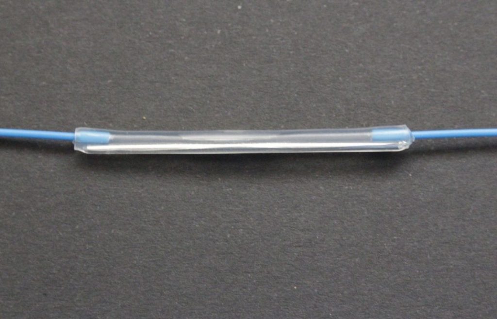
Mechanical Splicing Process
Mechanical splicing joins two optical fibres using an adjusting device and index-matching gel, a quicker method than fusion splicing.
Inserting Fibres into the Splice Sleeve
The first step is to insert the prepared fibre ends into the splice sleeve, aligning them precisely to give smooth light transmission.
Proper insertion avoids gaps that could lead to signal loss.
Securing and Aligning Fibres
Once inserted into the splice sleeve, the fibres need to be secured in place using mechanical splicing tools that hold the fibres firmly while maintaining alignment.
Accurate matching minimises signal loss and provides a stable connection.
Crimping or Heating the Splice
The final step is securing the splice permanently, either by crimping the splice sleeve or using a heat shrink process.
Crimping compresses the sleeve around the fibres, while heat shrinking tightens the sleeve around the splice.
Both methods protect the splice from environmental factors and physical damage.
Mechanical splicing provides a quick and effective way to join optical fibres, especially when speed and simplicity are essential.
By following these steps, technicians can achieve reliable connections with minimal signal loss.
Testing and Quality Assurance
The quality of fibre optic splices is required for maintaining network performance.
Proper testing and quality assurance procedures help identify and address issues affecting signal transmission.
Optical Loss Testing
Optical loss testing measures signal loss at the splice point.
This test is performed using an optical time-domain reflectometer (OTDR) or a power meter and light source.
The OTDR sends a light pulse down the fibre and measures reflected signals, identifying any loss or reflections caused by the splice.
Low loss indicates a good splice; high loss may require re-splicing or further inspection.
Visual Inspection for Quality
Visual inspection involves examining the splice and fibre ends using a fibre inspection microscope to identify issues such as cracks, misalignment, or dirt that could affect splice quality.
A thorough inspection makes sure fibres are clean and aligned before finalizing the splice. Proper cleaning and preparation are essential for high-quality splices.
Verifying Splice Integrity
Verifying splice integrity involves checking the mechanical strength and stability of the splice by gently pulling so it holds firmly.
The splice protection sleeve should be checked for proper application and security.
The mechanical soundness helps prevent future issues like signal loss or fibre breakage.
Comprehensive optical loss testing, visual inspections, and integrity verification mean that fibre optic splices meet required quality standards, maintaining network performance and reliability.
Troubleshooting Common Issues
Effective troubleshooting is essential for maintaining the performance and reliability of fibre optic networks.
Identifying and addressing common splicing issues can prevent network downtime and signal loss.
Identifying and Fixing Splice Failures
Splice failures can occur due to improper alignment, dirt on the fibre ends, or equipment malfunctions.
To identify splice failures, use an optical time-domain reflectometer (OTDR) to detect high loss or reflections at the splice point.
Once identified, re-clean the fibre ends, realign them carefully, and perform the splice again. This provides a clean and precise splice that can significantly reduce the risk of failure.
Dealing with Fibre Breaks
Fibre breaks can happen during installation or maintenance due to bending, pulling, or accidental cuts.
To deal with fibre breaks, first locate the break using an OTDR or visual fault locator.
Once located, cut out the damaged section, prepare the fibre ends, and perform a splice.
Using appropriate handling techniques and tools can help prevent future breaks and provide a strong connection.
Addressing Signal Loss
Signal loss can be caused by poor splicing, dirty connectors, or damaged fibres.
To address signal loss, start by testing the fibre with an OTDR to pinpoint the location and cause of the loss.
Clean all connectors and re-splice any identified problem areas.
Make sure that fibres are properly cleaved and aligned during splicing to minimize loss.
Regular maintenance and proper splicing techniques are key to reducing signal loss.
By systematically identifying and fixing splice failures, dealing with fibre breaks, and addressing signal loss, technicians can maintain the integrity and performance of fibre optic networks.
These troubleshooting steps are essential for reliable data transmission and network stability.
Applications of Fibre Optic Cable Splicing
Fibre optic cable splicing is used in various industries to support high-speed data transmission and reliable communication networks.
Understanding these applications highlights the need for effective splicing techniques.
Telecom and Data Networks
In telecommunications, fibre optic splicing is needed for creating long-distance connections that support high-speed internet and phone services.
Splicing helps extend the reach of telecom networks, and continuous and efficient data flow.
Data centres also rely on fibre optic splicing to manage large volumes of data, facilitating rapid data transfer between servers and storage systems.
Cable TV and Internet Services
Cable TV and internet service providers use fibre optic splicing to deliver high-definition video and fast internet speeds to homes and businesses.
By splicing fibres, providers can expand their networks and improve service quality.
This means that customers receive consistent and high-quality service, essential for streaming, online gaming, and other data-intensive activities.
Industrial and Military Applications
Fibre optic splicing is needed in industrial settings, where it supports communication systems in factories, power plants, and other facilities.
These environments often require strong and reliable connections to handle operations.
In the military, fibre optic splicing is used for secure and fast communication links, supporting various applications from field communications to radar systems.
Splicing fibre optic cables in these applications requires precision and adherence to strict quality standards for strong performance and reliability.
Understanding the specific needs and challenges of each application helps technicians choose the right splicing methods and tools, contributing to the overall success and efficiency of the networks.
Best Practices and Safety Measures
Adhering to best practices and safety measures is essential for successful and safe fibre optic splicing.
Proper techniques and precautions help with high-quality splices and protect technicians.
Safety Precautions for Splicing
Safety is required when working with fibre optics.
Always wear safety glasses to protect your eyes from glass shards and laser light. Use a well-ventilated area to avoid inhaling any fumes from the splicing process.
Keep a clean workspace to prevent contamination of the fibre ends.
Dispose of fibre scraps properly, as they can cause injury if handled carelessly.
Tips for Efficient and Reliable Splicing
Efficient splicing requires attention to detail and the right techniques.
This means fibres are clean and free of dust before splicing.
Use high-quality tools and maintain them regularly for optimal performance.
Follow the manufacturer’s instructions for splicing equipment to achieve consistent results.
Practice proper fibre handling techniques to avoid bends or breaks that can compromise the splice quality.
Maintaining Splice Records and Documentation
Keeping accurate records of each splice is required for future reference and maintenance.
Document the splice location, type, and test results.
This information helps in troubleshooting any issues that arise later and consistency across the network.
Use splice trays and organisers to keep splices neatly arranged and easily accessible.
By following these best practices and safety measures, technicians can achieve reliable splices and maintain a safe working environment.
Proper documentation and adherence to recommended techniques contribute to the long-term performance and reliability of fibre optic networks.
Fibre optic cable splicing is an essential technique for maintaining reliable and efficient network connections.
By understanding the different types of splices, components of fibre optic cables, and the tools required, technicians can perform splicing effectively.
Preparation steps, including inspection, cleaning, stripping, and cleaving, are for achieving high-quality splices.
Both fusion and mechanical splicing methods have their unique advantages and are used based on specific needs.
Testing and quality assurance means that splices meet the required standards while troubleshooting addresses any potential issues.
The various applications of fibre optic splicing, from telecommunications to industrial settings, underscores its effectiveness.
Following best practices and safety measures not only improves splicing quality but also provides a safe working environment.
Accurate documentation supports ongoing maintenance and troubleshooting efforts.
By adhering to these guidelines, technicians can support the performance and reliability of fibre optic networks.
For more information or assistance with your fibre optic splicing needs, feel free to contact us.