Printed Circuit Boards (PCBs) serve as the quintessential foundation of electronic devices, orchestrating the connectivity of various electronic components through meticulously etched electrical paths on copper sheets.
These boards are pivotal in the realm of modern electronics, underpinning the functionality of a myriad array of devices by facilitating the integration of resistors, capacitors, and integrated circuits.
The essence of how PCBs function rests on their intricate design and layout, and PCB assembly which are paramount in dictating both the operational efficiency and performance of the end product.
As we dive into the mechanisms of how do PCB boards work and how does a PCB work, it becomes evident that PCBs are not just mere platforms for component assembly but are critical in ensuring the seamless operation and reliability of electronic systems.
This introduction aims to equip engineers and electricians with a profound understanding of PCB functionality, underscoring their indispensable role in the advancement of electronic engineering.
What is a PCB?
Printed Circuit Boards (PCBs) are ingeniously crafted as multi-layered entities, composed of non-conductive substrates that are laminated with conductive copper tracks.
These tracks ingeniously replace traditional wiring, enabling an efficient interconnection between various electronic components.
PCBs manifest in various forms, including single-sided, double-sided, and multi-layered types, each tailored to meet the diverse complexities and applications prevalent within the electronics industry.
A pivotal aspect of how PCB works lies in its ability to offer a meticulously structured platform for the mounting of electronic components.
This ensures not only a predictable performance but also facilitates a straightforward approach on how to check if a PCB is working, by precisely defining the electrical connectivity among the components.
Such a foundation is crucial for the reliability and functionality of electronic devices, underscoring the PCB’s indispensable role in modern electronics.
How does a printed circuit board work?
Connection of PCBA traces to components
Due to the intricacies of printed circuit boards, traces, or copper pathways, play a key role in forming the connections between electronic components, thus enabling the flow of electric currents and signals across the board.
The efficiency of these connections, critical for the signal integrity and overall performance of the electronic device, is significantly influenced by the PCB design.
A well-conceived design ensures that signals are transmitted with minimal loss and interference, thereby enhancing the device’s functionality and reliability.
Additionally, the process of soldering components onto the PCB is crucial for establishing a secure and conductive link to these traces.
This meticulous procedure ensures that each component is firmly connected, further bolstering the PCB’s role as the backbone of electronic circuitry.
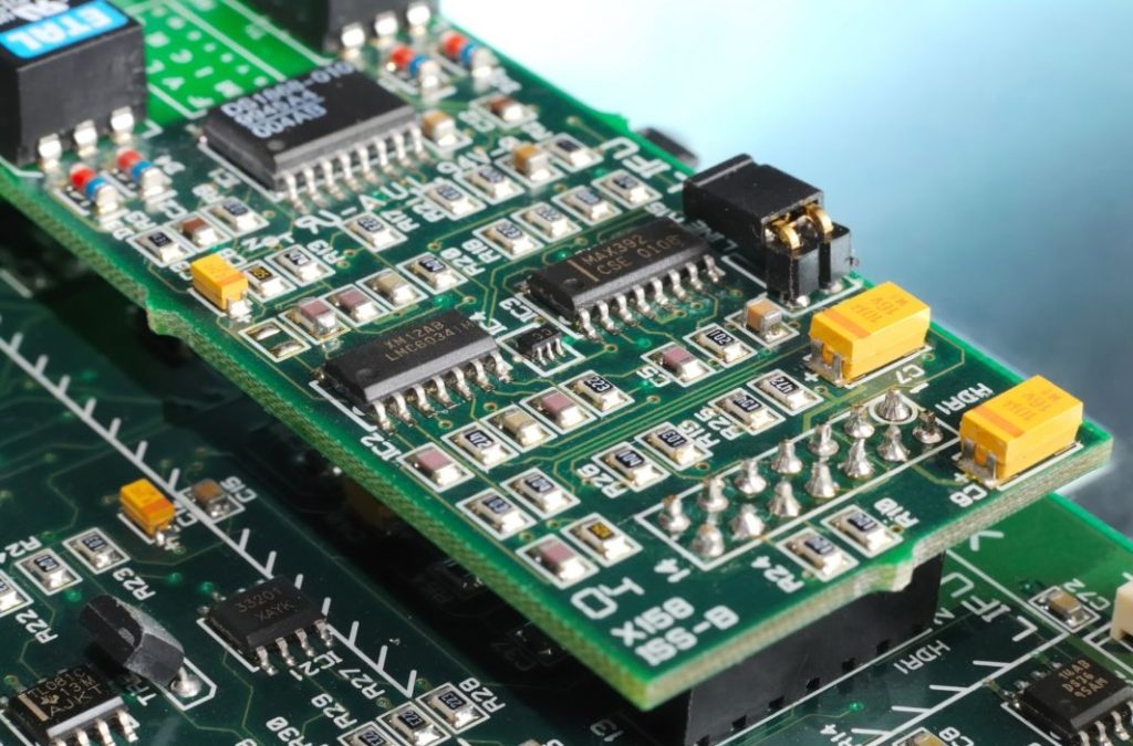
PCB Board Compositions
The composition of Printed Circuit Boards (PCBs) is fundamental to their functionality and performance.
At the heart of a PCB is the base material, usually fibreglass, renowned for its insulating properties and structural integrity.
Laminated atop this substrate is a copper layer, which forms the conductive pathways for electrical signals.
A solder mask is then applied, serving both to protect the copper traces from oxidation and to prevent solder bridges between closely spaced conductive pads.
The final layer, the silkscreen, adds human-readable labels and symbols to assist in the assembly and testing of the board.
The choice of these materials, alongside the board’s meticulous layout, is critical not only for ensuring efficient thermal management and durability but also for optimising the electrical performance of the PCB.
This careful selection and arrangement underpin the board’s ability to reliably function in a wide range of electronic devices.
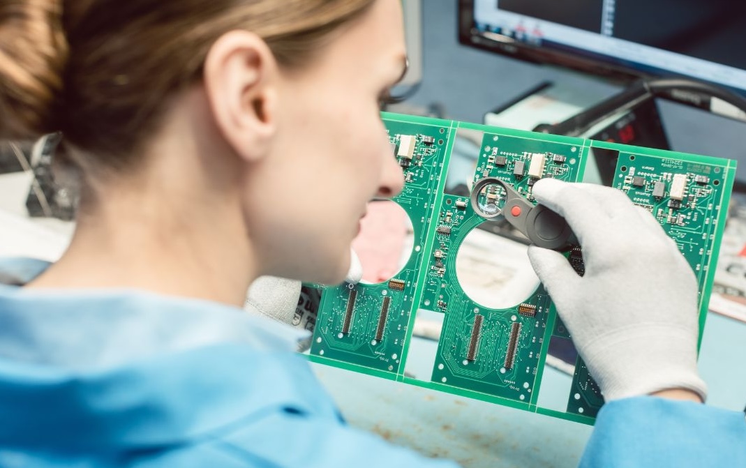
How to check if a PCB is Working?
Check the schematic accuracy
Ensuring the accuracy of a Printed Circuit Board (PCB) begins with a meticulous verification of the schematic diagram against the actual PCB layout.
This critical step confirms that all connections are correctly implemented and free from errors, a fundamental aspect of the board’s functionality.
To facilitate this process, the utilisation of sophisticated software tools for schematic capture and layout verification is highly recommended.
These tools enable engineers and electricians to identify and rectify potential issues in the design phase, well before the PCB is fabricated.
Such preemptive measures are indispensable in avoiding costly revisions and ensuring the PCB operates as intended, highlighting the importance of thorough validation in the PCB design and manufacturing process.
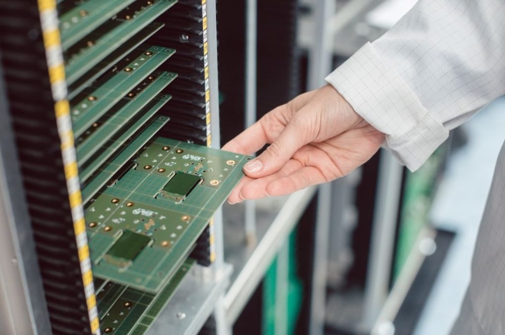
Accuracy of Component Installations
A crucial aspect of Printed Circuit Board (PCB) assembly involves the meticulous inspection of component placement and orientation, ensuring each aligns perfectly with the design specifications and is properly soldered.
This scrutiny is essential, as even minor discrepancies can lead to significant functionality issues.
Common errors that require vigilance include misplaced components, which may not align with the intended circuit path, reversed components that disrupt the flow of current, and incorrectly soldered components that could lead to faulty connections.
Identifying and rectifying these errors before final testing is paramount in safeguarding the PCB’s operational integrity and ensuring its expected performance within electronic devices.
Electric Observations
The meticulous testing of Printed Circuit Boards (PCBs) is paramount in ensuring their functionality and reliability.
Engineers and electricians employ a range of sophisticated electrical testing equipment, including multimeters and oscilloscopes, to measure voltage, current, and signal integrity across various points of the PCB.
This comprehensive analysis is vital for identifying potential issues such as short circuits, open circuits, or deviations from expected signal characteristics.
By meticulously scrutinising the PCB’s performance using these tools, professionals can detect and rectify any anomalies that could compromise the operational integrity of the electronic device, underscoring the critical role of testing in the PCB manufacturing process.
Printed Circuit Boards (PCBs) are integral to modern electronics, relying on precise design, fabrication, and testing processes.
Engineers and electricians must appreciate their complexity, as ongoing advancements aim for higher efficiency and integration to meet industry demands.
Understanding the intricate workings of Printed Circuit Boards (PCBs) is paramount for engineers and electricians in the ever-evolving field of electronics.
For further inquiries or assistance, do not hesitate to contact us.
We are here to support your endeavours in mastering PCB technology and advancing your projects.